

Overview:
In this project, I will tell you how to build a Portable IoT based Fingerprint Biometric Attendance System using NodeMCU ESP8266 12E, 0.96” OLED Display & SFG R303a Fingerprint Sensor. The ESP8266 Wi-Fi Module will collect the fingerprint data from multiple users and sends it over the internet to a website. The Enrolment of fingerprints is done on the server using any fingerprint sensor like R303, R305 or R307 that is available on the market and verification of the fingerprint will be done on the webserver while fingerprint templates are transmitted over the WiFi.
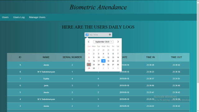
The website used in this project is developed using PHP; it has a database and records of attendance. By logging into the website, you can collect all the attendance records of each user, including personal details as well as incoming & outgoing timing. The data can also be downloaded and exported to an excel sheet.

Website: a snapshot of Portable IoT Based Fingerprint Biometric Attendance System
The main drawback of conventional authentication technologies like RFID tags and authentication cards are can be transferred, if we use such type of methodologies users can easily manipulate the data, biometric method of authentication is a prompt replacement for this. Biometrics such as fingerprints, Face Recognition, voice and ECG signals are unique human characters that cannot be tampered or replicated impossible to manipulate. This allow us to develop rugged real-time biometric system implementations.
Required Components:
The following are the required components to proceed with IoT Based Biometric Fingerprint Attendance System. All the components can be purchased from Amazon. The purchase links are given below.
In this article, I am using the SFG r303a module. Currently, this module is not in production. you can R305 or R307.
- NodeMCU Buy from Banaao
- R303/R305/R307 fingerprint sensor Buy from Banaao
- 0.96″ OLED display Buy from Banaao
- Li-Ion battery(18650) Buy from Banaao
- TP4056 Li-Ion Battery charger Buy from Banaao
- MT3608 Boost converter Buy from Banaao
- On/Off switch Buy from Banaao
- Breadboard Buy from Banaao
- Connecting wires Buy from Banaao
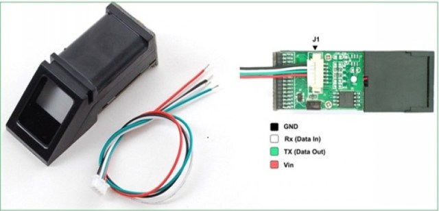
SFG R303 Fingerprint Identification Module
Introduction
This is a fingerprint sensor module with a TTL UART interface for direct connections to microcontroller UART or to PC through MAX232 / USB-Serial adapter. The user can store the fingerprint data in the module and can configure it in 1:1 or 1: N mode for identifying the person.
The Fingerprint module can be directly interfaced with any microcontroller as well as Arduino Board. This optical biometric fingerprint reader with great features and can be embedded into a variety of end products like access control system, attendance system, safety deposit box, car door locking system
Operation Principle:
Fingerprint processing includes two parts: fingerprint enrollment and fingerprint matching (the matching can be 1:1 or 1:N).
When enrolling, the user needs to enter the finger two times. The system will process the two-time finger images, generate a template of the finger based on processing results and store the template. When matching, the user enters the finger through the optical sensor and the system will generate a template of the finger and compare it with templates of the finger library. For 1:1 matching, the system will compare the live finger with a specific template designated in the Module; for 1:N matching, or searching, the system will search the whole finger library for the matching finger. In both circumstances, system will return the matching result, success or failure.
Features
- Integrated image collecting and algorithm chip together, ALL-in-One
- The fingerprint reader can conduct secondary development, can be embedded into a variety of end products
- Low power consumption, low cost, small size, excellent performance
- Professional optical technology, precise module manufacturing techniques
- Good image processing capabilities can successfully capture image up to resolution 500 dpi
Specifications:

For more information about the SFG R303A Fingerprint sensor, check out this datasheet.
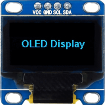
0.96″ I2C OLED Display:
This is a 0.96 inch blue OLED display module. The display module can be interfaced with any microcontroller using SPI/IIC protocols. It is having a resolution of 128×64. The package includes display board, display,4 pin male header pre-soldered to board.
OLED (Organic Light-Emitting Diode) is a self light-emitting technology composed of a thin, multi-layered organic film placed between an anode and cathode. In contrast to LCD technology, OLED does not require a backlight. OLED possesses high application potential for virtually all types of displays and is regarded as the ultimate technology for the next generation of flat-panel displays.
Specifications:
- OLED Driver IC: SSD1306
- Resolution: 128 x 64
- Visual Angle: >160°
- Input Voltage: 3.3V ~ 6V
- Compatible I/O Level: 3.3V, 5V
- Mini Size: 2.7 x 2.8cm
- Only Need 2 I/O Port to Control
- Fully Compatible with Arduino
- Working temperature: -30°C ~ 70°C
- Module volume ( generous ): 27.0 x 27.0 x 4.1mm
- Factory configured for SPI protocol (can be easily changed to IIC)
For more information about the SSD1306 OLED Display, check out this datasheet.
The Total process includes the following steps:
- Setting up the website
- Circuit Diagram and hardware connections
- Source code development
- Registration of the users.
Setting up the website:
The website used in this project can be configured as global/Local. You need to have a unique domain name and to set up a global website. if you have a website and a server you can simply download the biometricattendance.zip file and copy to the cPanel/website file manager and modify the connectDb.php and install.php files with your website credentials. but having a website domain and hosting is will cost you more.
In case if you don’t wanna spend money on website management, then you can configure your website as local and use your own computer as a server to store the data locally in localhost.
For that, you can use any local server provider Xampp or Wamp. I have given both download links below you can choose either.
Download and install Xampp from the link here: Download XAMPP
Download and install Xampp from the link here: Download Wamp
I will use Xampp to demonstrate further process. Choose an appropriate file for your operating system. Xampp is available for Windows, Linux Mac.
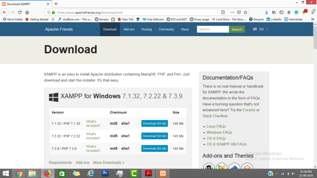
Once the file is downloaded successfully install the Xampp, the installation process is very easy, it is like normal software installation only.
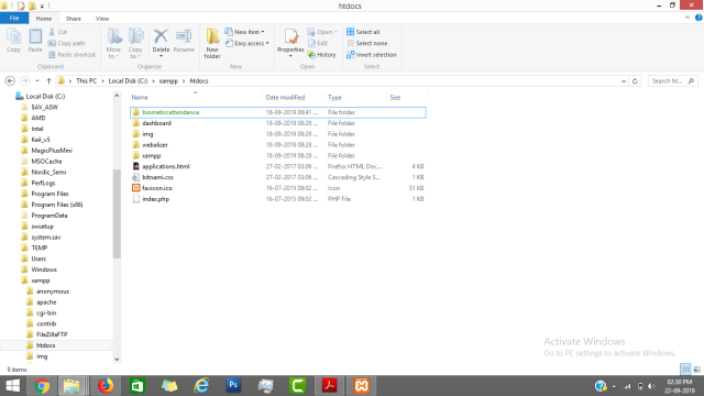
After successful installation, simply download the biometricattendance.zip file and copy to folder C:\xampp\htdocs in your computer. This folder is the location where all your website data will store.
The website configuration process is a little bit longer, which is explained in the video. You can follow the video to completely set up the website.
Circuit Diagram: Portable IoT based Fingerprint Biometric Attendance System
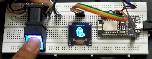
The following circuit diagram shows how an OLED Display & Fingerprint Sensor is interfaced to NodeMCU ESP8266 12E Board.
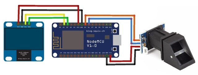
The I2C pins of OLED Display, i.e SDA & SCL is connected to NodeMCU D1 & D2 pins respectively. Similarly, the fingerprint sensor is also connected to UART pins D5 & D6. The fingerprint sensor Tx and Rx wires color may vary. So connect it by finding appropriate color wires else the module won’t be detected by NodeMCU.
The R303a fingerprint sensor is supplied with 5V through Vin pins of NodeMCU. In my case, the sensor didn’t work at 3.3V. because sensor operating voltage is 3.6v to 6v Similarly, connect OLED Vcc pin to 3.3V of NodeMCU.

Source Code/Program
The source code for the Portable IoT Based Fingerprint Biometric Attendance System using NodeMCU here.
In this source code, you need to do two modifications according to your WiFi Network connection and PC IP.
You have to make sure that the WiFi username and password are provided which is available in the range.
/* Set these to your desired credentials. */
const char *ssid = “Electronics_Innovation”; //ENTER YOUR WIFI SETTINGS
const char *password = “subscribe”;
Also, change the IP Address if you are using Xampp or change the website domain name if you are using the global website as changed below.
String link = “http://192.168.43.205/biometricattendance/getdata.php”; //computer IP or the server domain
Add the following libraries via library manager or simply add the following zip files to Arduino libraries folder:
1. OLED GFX Library: Download
2. SSD1306 Library: Download
3. Adafruit Fingerprint Sensor Library: Download/*Developed by Electronics InnovationProject: Portable IoT based Fingerprint Biometric Attendance System with NodeMCU.Electronics Innovation -=======================================================
Registration of users:
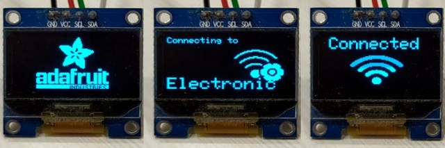
Once the Program successfully uploaded to the NodeMCU, It will boot up with the Adafruit logo and then ModeMCU will try to establish the connection between the WiFi router which is provided in the program. Once it gets Connected it will display Connected. The same log can be seen on the Serial Monitor as well as in OLED Display.
So now you can start the registration process of the user on the website using the following link: http://localhost/biometricattendance/ManageUsers.php

The whole process of registration is explained very well in the video. You can follow the video for the complete registration process. The user fingerprint is taken twice i.e as mentioned in the datasheet and stored in EEPROM of Fingerprint Sensor. It is to be noted that only 127 fingerprints can be stored in this R303/R305/R307 module.


Pic: User registration Step1_ScanningPic: User registration Step1_Remove finger
Pic: User registration Step1_Fingerprint has been added.
Authentication of Users:
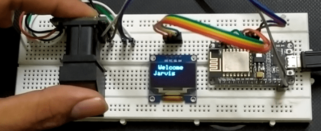
So once the User registration process is completed, you can start scanning and marking the attendance. If a registered user scans his/her finger for the first time on that day, It will display the welcome message as follows.
If a registered user scans his/her finger for the second time on that day, It will display the goodbye message as follows.

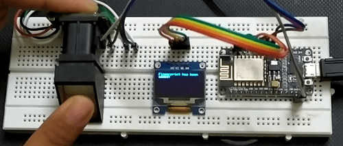
In case if the fingerprint is not matched or an unregistered candidate tries to authenticate it will display an error message as shown in the figure below.
Finally, you can access the entire Attendance data of the Students/Employee on the website by simply selecting the particular date as shown below, You can also download the same data in excel format by clicking on the Export to Excel button.
Realtime implementation of Portable IoT based Fingerprint Biometric Attendance System:
I wanted to take this project to the next level i.e Real-Time implementation, This includes additions circuitry and mechanical parts like Battery, Battery management system, Boost converter and a casing. but there will be no change in the Firmware(Source code)
Since R303a Fingerprint sensor will not work on 3.3v we need to have 5V supply, on the other hand, we should have rechargeable battery i.e Li-ion battery whose voltage is not sufficient to drive the R303a Fingerprint sensor. So I decided to add one boost converter(MT3608) to the circuitry to get 5v.
After these modifications circuit will be like this.
Realtime implementation circuit.

FInal Circuit: Portable IoT based Fingerprint Biometric Attendance System
I made one casing with the wooden stripers to keep all the circuitry in that just have a look at this. I showed this process in the video you can experience it there.
The dimensions for this box are 7x8x5 (cm), I cut down some area on the front part to accommodate the Fingerprint sensor and OLED display.
Final results:
Final product: Portable IoT based Fingerprint Biometric Attendance System
You can follow the video to understanding the whole process like how to add, update and remove the users from the database, how to access the attendance data, how to export the attendance data to the excel. This video will help you through the journey of making Portable IoT Based Fingerprint Biometric Attendance System.